This protocol describes echocardiography assessment of cardiac structure, function, and pulmonary hypertension in a lamb model of evolving bronchopulmonary dysplasia. The method enables serial evaluation of cardiopulmonary disease and may be applied to other large-animal models of neonatal and adult cardiovascular disease.
Method Article
Echocardiography Assessment of Cardiac Function and Pulmonary Hypertension in Lambs
* These authors contributed equally
Opens in a new tab
In This Article
Summary
Loading...
$$\rightleftharpoonup{xx}$$
$$\longleftharp{xx}$$,
$$\longrightharp{xx}$$,
Abstract
Loading...
$$\rightleftharpoonup{xx}$$
$$\longleftharp{xx}$$,
$$\longrightharp{xx}$$,
Premature birth is strongly associated with cardiac dysfunction, including impaired ventricular function and altered cardiac structure, which can lead to progressive heart failure and other short- and long-term morbidities. However, the natural history of cardiac dysfunction in infants born prematurely is not well defined. In the lamb model of bronchopulmonary dysplasia with associated pulmonary hypertension (BPD-PH), lambs are delivered at 110–128 days gestation (full term is approximately 145 days) and mechanically ventilated. The lambs develop cardiopulmonary complications of prematurity, including alveolar simplification on lung histology, the hallmark of BPD, and signs of increased pulmonary vascular resistance on echocardiography, consistent with evolving BPD-PH. This article describes a protocol for serial assessment of cardiac morphometry and function by echocardiography in preterm and former preterm lambs (up to approximately two months postnatal age). The protocol was developed by adapting guidelines from the American Society of Echocardiography. Echocardiography is serially performed on intubated and moderately sedated lambs using a bedside ultrasound system. Atrial and ventricular dimensions, right and left ventricular function, and PH-related measurements are obtained at each echocardiographic assessment. Measurements are reproducible and correlate with clinical status. This echocardiography protocol for assessing cardiac structure and function in lambs enables characterization of BPD-PH and evaluation of therapeutic approaches.
Introduction
Loading...
$$\rightleftharpoonup{xx}$$
$$\longleftharp{xx}$$,
$$\longrightharp{xx}$$,
The lamb model of evolving bronchopulmonary dysplasia and pulmonary hypertension (BPD-PH) replicates both the developmental lung stage and clinical care setting experienced by preterm infants in the neonatal intensive care unit (NICU). In the lamb model of evolving BPD-PH, lambs are delivered across a range of gestational ages from 110 d gestation (late canalicular phase of lung development, equivalent to 22–24 weeks gestation) through term (145 d) and mechanically ventilated. Lambs are followed for up to six months for the development of cardiopulmonary disease. This model recapitulates pathophysiology and histopathology resulting from mechanical ventilation with oxygen-rich gas in preterm neonates, including alveolar simplification and thickened septae1. The strength of the lamb model of BPD-PH is its similarity to human developmental lung stages and the relatively large size of lambs, which allows for frequent blood draws and the use of clinical tools imported directly from the NICU2. Here, we report a protocol for serial echocardiography for the assessment of cardiac function and pulmonary hypertension (PH) in lambs.
BPD-PH is a common and significant cardiopulmonary complication in survivors of preterm birth3,4,5. Infants born at lower gestational ages and birth weights are at highest risk for BPD and BPD-PH3. BPD-PH occurs when abnormal lung development secondary to prematurity and mechanical and oxidative stress leads to vascular remodeling over the course of several months4. This contributes to increased pulmonary vascular resistance, resulting in right ventricular strain and, in severe cases, failure, ultimately increasing morbidity and mortality in later infancy and early childhood5.
Echocardiography allows for noninvasive serial assessment of several anatomical and physiological features of both the right and left ventricles. The American Society of Echocardiography has published guidelines for pediatric transthoracic echocardiograms6,7. Similar guidelines do not exist for preclinical models such as the neonatal lamb model of BPD-PH. Here, we present an echocardiography protocol modified for the neonatal lamb model. While the anatomy of the lamb thorax and abdominal compartment limits the ability to obtain subcostal views, apical and parasternal views are readily obtainable. These views allow for comprehensive evaluation of cardiac function and PH using multiple parameters, including ventricular septal position, pulmonary artery acceleration time (PAAT), tricuspid annular plane systolic excursion (TAPSE), tricuspid regurgitation, right ventricular (RV) fractional area of change (FAC), and left ventricular (LV) ejection fraction (EF). Furthermore, we correlated echocardiographic measurements with clinical status and cardiac catheterization results, validating the utility of echocardiography as a noninvasive method of cardiac assessment in the lamb model of BPD-PH.
Access restricted. Please log in or start a trial to view this content.
Protocol
Loading...
$$\rightleftharpoonup{xx}$$
$$\longleftharp{xx}$$,
$$\longrightharp{xx}$$,
All experimental procedures were performed in compliance with the animal handling and training standards of the University of Utah’s Institutional Animal Care and Use Committee.
1. Procedure setup
- Position the lamb in a sling in the prone position.
- Position the echocardiographer on the left side of the lamb for most echocardiographic views described in this protocol, unless otherwise noted.
- Place the ultrasound machine toward the head of the sling setup so that the echocardiographer can interface with the controls using the left hand and hold the transducer in the right hand.
- Use an assistant to help position the lamb, with the assistant positioned on the opposite side of the lamb. Refer to Figure 1 for the experimental setup and lamb positioning used for transthoracic echocardiographic image acquisition.
- Monitor oxygen saturation (SpO₂), arterial blood pressure, and heart rate throughout the procedure. Halt the procedure to allow vital signs to stabilize or abort the procedure if SpO₂ remains <90% for 2 min, heart rate is <60 beats/min, or respiratory rate is >100 breaths/min despite ventilator and inspired oxygen fraction adjustments, or if arterial blood pressure decreases by >15% from the pre-procedure baseline.
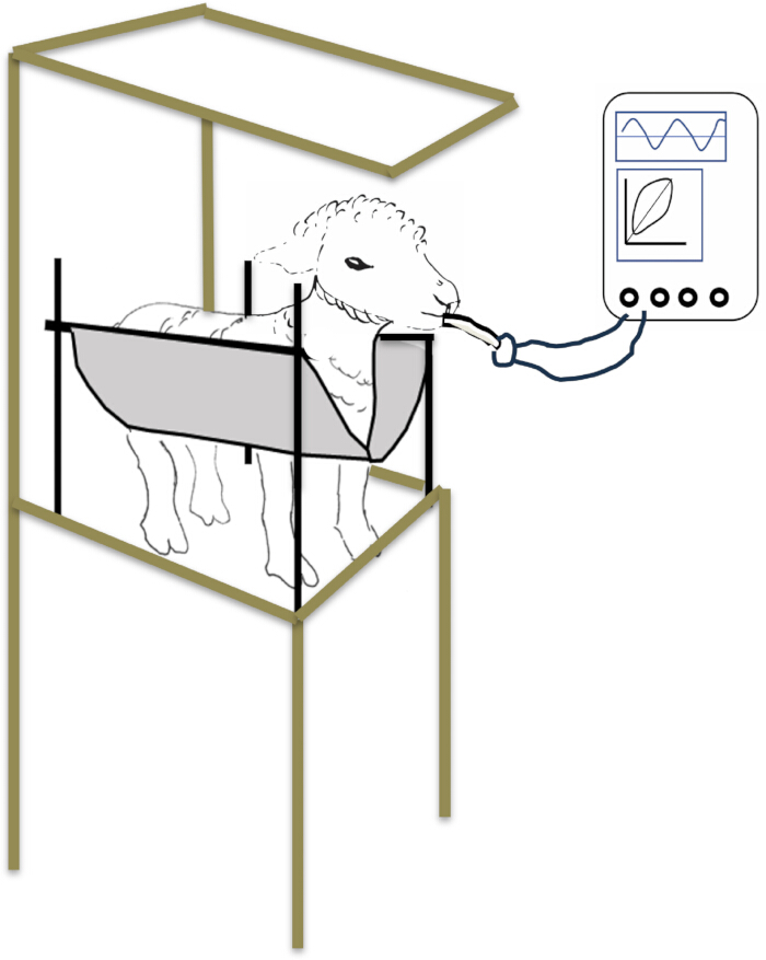
Figure 1. Experimental setup for transthoracic echocardiographic image acquisition in the lamb. Representative setup demonstrating lamb positioning within the sling. Please click here to view a larger version of this figure.
2. Ultrasound machine setup
- Record subject information, including identifiers, weight, and blood pressure (systolic, diastolic, and mean).
- Select the desired transducer. For lambs, use a 12S (5–11 MHz) phased-array cardiac transducer.
- Select ultrasound presets for cardiac imaging, if available.
NOTE: Maintain consistent physiologic conditions (e.g., heart rate, respiratory status, and level of sedation) during echocardiographic acquisition, as these factors can influence Doppler-derived measurements.
3. Lamb positioning and transducer position
- The precise lamb position and transducer position required to obtain standard transthoracic echocardiographic views can vary depending on gestational age at birth, postnatal age, lung inflation, and abdominal distention.
- Start in the prone position with the lamb’s left leg naturally folded up against the thorax and resting in the sling, exposing the left axilla and thorax from below. Manipulate the lamb’s position in the sling as needed to obtain optimal views. If needed, position the lamb in a partial to full right lateral decubitus position within the sling.
- Apply ultrasonic gel to the transducer tip and the lamb chest wall to ensure optimal conduction of ultrasound waves.
NOTE: The views described below are typically obtained between the 3rd–6th intercostal spaces on the more ventral aspect of the thorax (i.e., toward the sternum).
4. Obtain standard apical views
NOTE: Apical views are more readily obtained in preterm and term lambs. In our experience, as lambs age beyond 2 months, the thorax enlarges and the apex of the heart moves farther away from the chest wall, making these views difficult to obtain from the left thorax.
- Position the transducer in the 5th–6th intercostal space.
- Point the transducer toward the right shoulder.
- Start with the transducer indicator pointing dorsally toward the lamb’s left ear.
- To obtain the standard apical four-chamber (A4C) view, fan the transducer tail caudally and rotate the transducer clockwise or counterclockwise as needed until the maximal outer margins of the right and left ventricles are visible and the right and left atria are visualized without foreshortening. In the optimal A4C view, the tricuspid and mitral valves are visible, but the left ventricular outflow tract (LVOT) is not (Figure 2A)6,7.
- Once the A4C view is obtained, obtain the following parameters:
- Record a cine loop of at least 3 cardiac cycles (5–7 cycles is preferred) for measuring RA and LA dimensions, RV dimensions, RV FAC, subjective assessment of septal position, and LV ejection fraction (which also requires the LV-focused apical two-chamber view described below)6,7.
- Measure TAPSE by aligning the cursor with the lateral tricuspid annulus and recording an M-mode tracing6,7,8.
- Measure Mitral Annular Plane Systolic Excursion (MAPSE) by aligning the cursor with the lateral mitral annulus and recording an M-mode tracing9.
- While maintaining the A4C view, add color Doppler and obtain the following parameters by positioning the cursor as parallel to the Doppler flow as possible (ideally with an angle of insonation of <20°):
- Assess tricuspid regurgitation presence and peak velocity by placing the region-of-interest box over the tricuspid valve, aligning the cursor parallel with the color signal through the tricuspid valve, and recording a continuous-wave Doppler tracing6,7.
- Assess mitral regurgitation presence and peak velocity by placing the region-of-interest box over the mitral valve, aligning the cursor parallel with the color signal through the mitral valve, and recording a continuous-wave Doppler tracing6,7,10.
- Measure mitral valve inflow E and A waves (E/A ratio) by placing the region-of-interest box over the mitral valve, aligning the cursor parallel with the color signal through the mitral valve inflow, positioning the sample gate at the tips of the open mitral valve leaflets during diastole, and recording a pulsed-wave Doppler tracing6,7,10.
- Obtain the LV-focused A2C view:
- While maintaining the A4C view and the apical position of the transducer, rotate the transducer counterclockwise around the LV axis (approximately 45°–90°) until the RA and RV drop out and the LV A2C view showing the LV and LA becomes visible (Figure 2B).
- Record a cine loop of at least 3 cardiac cycles (5–7 cycles is preferred) in the LV-focused A2C view, which is required for LV ejection fraction by Simpson’s method6,7,11.
NOTE: Additional assessments of mitral regurgitation and inflow can be obtained in the LV-focused A2C view using the methods described in Steps 4.6.2 and 4.6.3.
- Obtain the LVOT-focused apical five-chamber (A5C) view:
- Return to the standard A4C view and tilt the transducer anteriorly with slight rotational adjustments until the LVOT becomes visible (Figure 2C).
- Measure LVOT velocity time integral by aligning the cursor parallel with the LV outflow, placing the gate just proximal to the aortic valve annulus, and obtaining a pulsed-wave Doppler tracing to determine LVOT VTI. Use VTI and aortic valve annulus diameter (obtained on PLAX and described below in Step 6.2.2) to estimate left ventricular cardiac output (CO), as described in adults, using the following formula6,7,12,13:

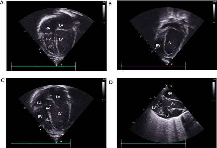
Figure 2. Representative apical and parasternal long-axis echocardiography views in the lamb. (A) Standard apical four-chamber (A4C) view at end-systole. (B) LV-focused apical two-chamber (A2C) view highlighting the LV and LA at end-systole. (C) LVOT-focused apical five-chamber (A5C) view demonstrating the left ventricular outflow tract. (D) Parasternal long-axis (PLAX) view including the aortic valve and ascending aorta. Ao, aorta; LA, left atrium; LV, left ventricle; LVOT, left ventricular outflow tract; RA, right atrium; RV, right ventricle. Please click here to view a larger version of this figure.
5. Obtain parasternal short-axis views (PSAX)
- Place the transducer between the 4th and 5th intercostal spaces near the sternum with the indicator oriented dorsally and slightly caudally.
- Fine-tune the PSAX view by sliding the transducer away from the sternum, applying slight rotation in either direction, and/or fanning the transducer tail cranially or caudally until a PSAX view of the aortic valve en face is visible (Figure 3A).
- With the aortic valve en face centered in the view, fan the transducer tail until the right ventricular outflow tract (RVOT) and pulmonary artery (PA) become visible (Figure 3B). Add color Doppler and obtain the following:
- Measure PAAT by using color Doppler to assess the direction of flow and image quality, aligning the cursor parallel to the flow, placing the gate just proximal to the pulmonary valve, and obtaining a pulsed-wave Doppler tracing (Figure 3D)13,14.
- Assess patent ductus arteriosus by evaluating its presence and direction of flow using color Doppler and pulsed-wave Doppler15.
- Return to the PSAX view of the aortic valve en face and fan the transducer tail toward the head to obtain the PSAX view at the level of the mitral valve. Continue fanning until reaching the level of the mid-papillary muscles (Figure 3C).
- Record a cine loop of at least 3 cardiac cycles (5–7 cycles is preferred) to assess intraventricular septum position and thickness and to measure left ventricular end-systolic eccentricity index (LVesEI) and the RV:LV end-systolic diameter ratio6,7.
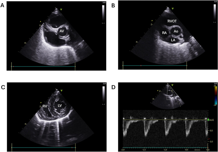
Figure 3. Representative parasternal short-axis echocardiography views in the lamb. (A) Parasternal short-axis view at the level of the aortic valve. (B) Parasternal short-axis view demonstrating the right ventricular outflow tract (RVOT) and pulmonary artery following transducer fanning. (C) Parasternal short-axis view obtained at the level of the mid-papillary muscles. (D) Representative pulsed-wave Doppler tracing of the pulmonary artery used for measurement of pulmonary artery acceleration time (PAAT). Ao, aorta; AV, aortic valve; LA, left atrium; PA, pulmonary artery; PAAT, pulmonary artery acceleration time; RV, right ventricle; RVOT, right ventricular outflow tract. Please click here to view a larger version of this figure.
6. Obtain parasternal long-axis views (PLAX)
- Fan the transducer back to the PSAX view of the aortic valve en face and rotate the transducer approximately 90° so that the indicator is positioned cranially to obtain a PLAX view (Figure 2D).
NOTE: Rocking the transducer tail cranially exposes more of the LV apex, whereas rocking the transducer tail caudally exposes more of the LVOT and ascending aorta.
NOTE: In either position, fanning the transducer tail upward (toward the vertebrae) exposes the LV inflow, whereas fanning the transducer tail downward (toward the legs) exposes more of the LVOT, aortic valve, and ascending aorta. - In the PLAX view, obtain the following parameters:
- Measure LV shortening fraction by aligning the cursor perpendicular to the long axis of the LV so that it crosses the minor axis of the LV at the mid-ventricle and recording an M-mode tracing6,7.
- Measure aortic valve annulus diameter by optimizing the PLAX view to visualize the LVOT and aortic valve. Record a cine loop of at least one cardiac cycle to measure the diameter of the aortic valve annulus at the valve hinge point at end-systole. Use this value along with VTI to estimate cardiac output, as described earlier6,7,12,13.
7. Obtain additional views from the right thorax
- Obtain additional PSAX and PLAX views from the right thorax as needed, using similar methods as described above.
Access restricted. Please log in or start a trial to view this content.
Results
Loading...
$$\rightleftharpoonup{xx}$$
$$\longleftharp{xx}$$,
$$\longrightharp{xx}$$,
The majority of the standard views recommended in the American Society of Echocardiography (ASE) pediatric echocardiography guidelines can be obtained in lambs. The standard A4C view, A2C view, and A5C view including the LVOT can be visualized (Figure 2A–2C). The parasternal long-axis view including the LVOT is also feasible (Figure 2D). A full complement of parasternal short-axis views, including views at the level of the aortic valve, pulmonar...
Access restricted. Please log in or start a trial to view this content.
Discussion
Loading...
$$\rightleftharpoonup{xx}$$
$$\longleftharp{xx}$$,
$$\longrightharp{xx}$$,
Echocardiography offers a noninvasive method to assess cardiac structure, function, and PH in lambs, including preterm and former preterm lambs (up to approximately two months corrected for gestational age) with evolving BPD-PH. A critical aspect of echocardiography in neonatal lambs is the use of a standardized protocol based on established guidelines and the application of the same rigor and best practices for image acquisition and measurement used clinically in human infants.
Other investig...
Access restricted. Please log in or start a trial to view this content.
Disclosures
Loading...
$$\rightleftharpoonup{xx}$$
$$\longleftharp{xx}$$,
$$\longrightharp{xx}$$,
The authors declare no relevant conflicts of interest.
Acknowledgements
Loading...
$$\rightleftharpoonup{xx}$$
$$\longleftharp{xx}$$,
$$\longrightharp{xx}$$,
We thank the Department of Pediatrics at the University of Utah for supporting our laboratory. We also acknowledge the many undergraduate students at the University of Utah who assisted with animal handling and made these studies possible.
Access restricted. Please log in or start a trial to view this content.
Materials
| Name | Company | Catalog Number | Comments |
|---|---|---|---|
| Phased-array cardiac transducer | GE | H44901AB | 12S-RS probe; 4.5–12.0 MHz |
| Sling for animal positioning | Made on site from heavy-duty fabric | N/A | Used to support lamb in prone position during imaging |
| Ultrasound gel | Parker Laboratories, Inc. | PLI 01-08 | Aquasonic 100 ultrasonic transmission gel |
| Ultrasound imaging system | GE | H48232DM | Vivid iq Vet v208 |
Reprints and Permissions
Request permission to reuse the text or figures of this JoVE article
Request Permission