This review critically evaluates difficult-to-standardize procedural elements of tDCS protocols, including device selection, electrode and scalp preparation, conductive medium, placement, fixation, and impedance management, and offers experience-based recommendations to reduce procedural variability and improve methodological consistency.
Review Article
From Protocol to Practice: Hidden Sources of Variability in Transcranial Direct Current Stimulation
Opens in a new tab
In This Article
Summary
Loading...
$$\rightleftharpoonup{xx}$$
$$\longleftharp{xx}$$,
$$\longrightharp{xx}$$,
Abstract
Loading...
$$\rightleftharpoonup{xx}$$
$$\longleftharp{xx}$$,
$$\longrightharp{xx}$$,
Transcranial direct current stimulation (tDCS) is widely used in neuroscience research and clinical contexts because it is non-invasive, relatively inexpensive, technically accessible, and has a highly favorable safety profile. However, its apparent simplicity can obscure implementation challenges and practical sources of variability that influence stimulation quality, participant comfort, reproducibility, and interpretation of results. Standard protocols typically specify current intensity, stimulation duration, electrode size, and montage, but less attention is often given to device selection, electrode preparation, conductive medium, hair and scalp management, impedance troubleshooting, electrode fixation, positioning accuracy, and operator-dependent decisions. These aspects are difficult to fully standardize because they depend on participant-specific factors, devices and consumables, and the operator's skills and experience. Nevertheless, they are central to protocol fidelity and should be treated as methodological variables rather than minor technical details. This review discusses practical challenges in implementing tDCS and provides experience-based recommendations for improving accuracy, quality, and consistency across sessions, participants, and research/clinical sites. The focus is on the “hidden” procedural steps that determine whether a nominally identical stimulation protocol is actually delivered in a comparable way. The discussion on these practical implementation aspects aims to complement existing safety and reporting guidelines and highlight the role of practical training in achieving reliable and reproducible tDCS delivery.
Introduction
Loading...
$$\rightleftharpoonup{xx}$$
$$\longleftharp{xx}$$,
$$\longrightharp{xx}$$,
Transcranial direct current stimulation (tDCS) is a widely used non-invasive brain stimulation technique that delivers a weak electrical current via electrodes placed on the scalp to modulate brain activity1. The stimulation intensities most commonly range from 1 to 2 mA, though studies have employed currents from approximately 0.5 to 4 mA, depending on the application2. Its broad adoption across basic and clinical neuroscience is supported not only by its scientific and therapeutic potential, but also by its practical advantages: tDCS devices are portable, relatively inexpensive, technically accessible, and well tolerated, with a favorable safety profile established across thousands of participants1,2. Compared with Transcranial Magnetic Stimulation (TMS), it offers lower equipment costs, the potential for at-home administration, and a broader eligibility profile due to fewer contraindications3. As a result, the use of tDCS has expanded considerably over the past two decades, a trend clearly reflected in bibliometric analyses of the field4,5. Conventional tDCS typically uses two electrodes positioned on the scalp6, although extracephalic return electrode placements are also used in certain experimental paradigms7, while high-definition tDCS (HD-tDCS) and other multielectrode protocols employ multiple smaller electrodes to achieve more targeted stimulation8. The use of both approaches is supported by a growing body of guidelines addressing safety, reporting, and methodological standards1,9,10,11.
Unlike TMS, which typically involves more built-in monitoring, such as neuronavigation and real-time motor-threshold feedback, tDCS’s low cost, portability, and technical simplicity are also what allow procedural execution to vary substantially across operators and sites without being flagged, making implementation-level variability a particularly consequential issue for tDCS specifically.
Namely, the apparent simplicity of tDCS can be misleading, and an important gap remains between methodological recommendations and the practical realities of implementing tDCS in research and clinical settings. Existing guidelines appropriately emphasize stimulation parameters, safety considerations, and reporting standards; however, they generally provide limited discussion of the procedural decisions that determine whether a protocol is delivered consistently in practice.
In other words, on paper, protocols are defined by parameters such as current intensity, stimulation duration, electrode size, and electrode montage. In practice, however, the quality and consistency of what is actually delivered depend on a range of procedural decisions that are rarely discussed in detail in published manuscripts, including how the device is selected and configured, how electrodes are prepared and what conductive medium is applied, how the scalp and hair are managed to ensure adequate contact, how electrode positions are identified and verified, how the setup is secured throughout the session, and how impedance is interpreted and addressed when problems arise12,13,14. Consequently, protocols that appear highly standardized in the literature may differ substantially in their practical implementation across participants, sessions, operators, and laboratories. In this review, the variability in these contextual and practical parameters is examined, with a focus on the procedural details that determine whether a nominally identical protocol is delivered consistently and reproducibly across participants, sessions, operators, and laboratories. These often-overlooked factors shape the fidelity of stimulation delivery and, consequently, may influence the observed effects of tDCS. Such implementation details are not peripheral to the protocol; rather, they determine whether the protocol is delivered as intended. The aim of this paper is to make explicit the tacit knowledge that experienced tDCS practitioners accumulate over time, but that is rarely captured in formal methodological reporting.
Existing guidelines addressing safety, ethical, legal, and reporting standards for transcranial electrical stimulation (tES) already provide comprehensive guidance on parameter specification and dosing1,9,10,11,15. This review is intended to complement them by focusing specifically on procedural execution, i.e., electrode preparation quality, scalp and hair management techniques, fixation trade-offs, and in-session troubleshooting, which is not systematically addressed elsewhere in the tDCS methodological literature. The review is expected to be of most direct benefit to researchers and clinicians new to tDCS, to trainees onboarding in a new laboratory, and to teams coordinating multi-site studies, where undocumented procedural variability is most likely to affect reproducibility. Although this review is scoped to tDCS, many of the procedural principles discussed extend to other tES modalities, including transcranial alternating current stimulation (tACS) and oscillatory tDCS (otDCS).
At the same time, this review bridges the gap between established empirical evidence and real-world execution by combining published literature with accumulated laboratory and clinical experience. This approach allows us to provide evidence-based strategies alongside experience-driven recommendations for nuanced procedural factors that have not yet been exhaustively evaluated in controlled trials.
Review and Perspective
Loading...
$$\rightleftharpoonup{xx}$$
$$\longleftharp{xx}$$,
$$\longrightharp{xx}$$,
Device selection
As the popularity of tDCS continues to rise, so is the number of commercial systems entering the market. All tDCS devices share core features: a battery-powered constant-current stimulator, electrodes with an electrolyte component, and headgear designed to secure electrode positions on the scalp16. Beyond this, however, devices differ substantially in other features, including impedance monitoring capabilities, sham delivery options, current-ramping flexibility, data logging, safety cutoffs, and compatibility with different electrode types and sizes. Research- and clinical-grade stimulators are typically required to meet formal regulatory and quality standards (including biocompatibility testing under ISO 10993-12717 and medical device certification such as CE marking or FDA clearance/approval, depending on jurisdiction and intended use) with documented current accuracy and safety cut-offs, whereas consumer-marketed devices are not necessarily subject to the same pre-market testing or ongoing quality assurance. These differences in device features have practical consequences that are often underappreciated. For instance, some devices impose a maximum current of 2 mA, whereas intensities of up to 4 mA have been shown to be well tolerated and are increasingly employed in research protocols; some systems are compatible with only one electrode type or size; and some commercial headsets offer only a limited set of predefined electrode positions. Protocols that require multi-channel delivery through smaller electrodes, such as HD-tDCS, impose their own compatibility constraints. In clinical and home-based settings, the feasibility of multi-electrode protocols may be further constrained by device capabilities and regulatory requirements, since devices used in clinical contexts must hold appropriate regulatory approval or clearance - a requirement that often translates into less flexible systems with greater manufacturer-imposed limits. Battery longevity and dependence on stable internet connectivity, where devices are software-controlled, are further factors that can affect session reliability in ways that are rarely acknowledged.
The key implication is that device selection should be guided by research aims rather than the other way around. In practice, this is not always achievable given resources and availability constraints. What is important is that device-related limitations are explicitly acknowledged in study reporting; that is, rather than being treated as background laboratory infrastructure, the device should be regarded as an integral part of the protocol, particularly when comparing findings across studies. Regardless of device choice, safety must remain a priority: battery-powered devices with optical isolation are preferred over mains-connected systems, as equipment malfunction in the latter may deliver uncontrolled current intensities without adequate protection18. All devices should be regularly maintained and operated by appropriately trained personnel.
Electrode properties and maintenance
Electrodes are the interface through which current is delivered, and their type, size, material, and preparation can affect current distribution, impedance, skin sensations, and stimulation fidelity. Although available electrode options have expanded in the last several years, the choice among them is rarely straightforward.
Electrode material
Conventional tDCS has traditionally used rubber electrodes enclosed in saline-soaked sponge pockets, and this configuration remains widely used. However, variability exists even within this category, with sponge materials differing in porosity and thickness6,19, thus affecting how much saline is needed, how quickly the sponge dries during a session, and how many times it can be reused across participants. Sponge electrode pockets have no established reuse limit and can generally be used over a long period (well beyond a single study, potentially for years) provided they are properly handled, cleaned, and stored between uses; they should be replaced once they show signs of degradation (e.g., worn, torn, or stiffened) rather than after a fixed number of sessions, as their usable lifespan depends heavily on sponge quality, handling, and storage practices.
Metal and silver/silver chloride (Ag/AgCl) electrodes are also employed, particularly in multielectrode setups such as HD-tDCS20. Reusable silver electrodes offer the advantage of lower impedance; however, they also have a shorter lifespan. While some suggest that when best practices are followed (including electrode rotation in 4x1 montages, consistent application of conductive gel, a proper saturation phase, and impedance monitoring), electrodes can be safely used for up to approximately 10 sessions20, manufacturer specifications may vary significantly. Still, in practice, electrodes are often used for much longer (if no change in signal quality is detected) or much shorter (if deterioration is observed; Figure 1) than recommended. Nonetheless, regular inspection before each use is necessary to identify potential defects that could compromise the delivery of stimulation. Additionally, to maintain their functionality and extend their lifespan, electrodes must be properly cared for, including thorough cleaning and drying after use.
Conductive medium
The choice of conductive medium is among the most consequential and least standardized aspects of tDCS preparation. Electrolyte-based conductive materials serve to facilitate uniform ionic conduction between the electrode and skin, reduce impedance, and minimize localized current density6. However, each available option presents a distinct set of trade-offs. Saline is inexpensive, readily available, and easy to apply, making it the most widely used conductor, reserved exclusively for rubber electrodes inserted into sponge pockets. However, pre-specifying the appropriate amount of saline is difficult. Namely, sponges that are too wet risk dripping and spreading across the scalp14, potentially creating unintended “bridging” between electrodes or producing uncontrolled current distribution; sponges that are too dry result in elevated impedance and non-uniform contact. Efforts to standardize saline application, by prescribing a fixed volume, e.g., 10–15 ml7 can be misleading, especially for inexperienced users, since the optimal amount depends on sponge type and size, room temperature and humidity, as well as hair properties14. Thicker or more absorbent sponges require a greater saline volume to reach saturation; smaller electrodes need smaller sponges, so a reduced volume is needed to avoid dripping. Lower room humidity accelerates evaporation, leading to greater impedance drift over the course of a session; if the room temperature is higher, it may cause faster evaporation of the saline and the need to apply additional amounts. The key takeaway is that, from the authors’ practical observations, the application should be informed by context and guided by experienced judgment, rather than executed rigidly. Due to risks of saline spreading, conductive gel and paste are more appropriate for smaller electrodes. Figure 2 illustrates the application and appropriate quantity for both conductive media.
Gel provides more stable contact with a lower risk of bridging than saline, though it can spread beyond the electrode boundary when compressed, effectively increasing the active contact surface in ways that are difficult to monitor or quantify. Conductive paste offers the most stable contact, particularly for smaller electrodes, providing the best fixation and adhering well to the skin, if hair allows. Paste is applied directly to the electrode and requires no mixing; however, it must be built up into a controlled, even layer that matches the electrode boundary. Achieving consistent thickness across that layer requires a certain level of skill and is therefore often prone to suboptimal execution in busy research environments. Inconsistent paste application may lead to uneven current delivery and increase the risk of localized skin reactions14. Notably, unlike saline or gel, paste is not absorbed by hair. Consequently, in participants with thick hair or scalp sites with dense hair coverage, achieving a stable contact surface may be more difficult21. Removal from skin and hair afterward is also more laborious than rinsing. Figure 3 represents proper and improper examples of applying conductive paste.
Electrode size
A related consideration is electrode size and its relationship to current density. Electrode size determines current density (current intensity divided by electrode area), which is constrained by established safety limits and therefore requires careful consideration. Most human studies operate within a current-density range of approximately 0.04–0.06 mA/cm2. However, the effective contact area does not always correspond to the nominal electrode dimensions. For example, sponge pockets surrounding the electrode may substantially increase the effective contact area if they are excessively thick (Figure 4). Similarly, when conductive gel spreads beyond the intended electrode boundary, the actual contact surface becomes larger than intended (Figure 4).
Conversely, sponge pockets should not be excessively thin, as this may increase cutaneous sensations during stimulation. A sponge thickness of approximately 0.5 cm is generally considered optimal8, although commercially available sponges typically range from 0.1 to 0.8 cm19. Comparable issues may also arise with other electrode types and conductive media. For example, compressed conductive gel can spread beyond the intended electrode boundary, increasing the effective contact area. In contrast, when conductive paste is used, insufficient pressure from the fixation system or dense hair may reduce or unevenly distribute the actual contact area, resulting in poorer and less consistent electrode contact.
Electrode size and type should be selected according to the intended montage and stimulation protocol. Square rubber electrodes measuring 5 × 5 cm or 5 × 7 cm remain the most commonly used configuration for conventional 1 × 1 tDCS22, although circular electrodes have become increasingly popular because square geometries tend to concentrate current at their corners. In contrast, multielectrode montages commonly employ smaller electrodes, with the 4 × 1 ring configuration representing one of the most frequently used arrangements. Electrode size, therefore, reflects a balance between stimulation focality (smaller electrodes) and lower peak current density (larger electrodes). Furthermore, the increased targeting precision offered by multielectrode configurations also demands greater placement accuracy, making these systems inherently more susceptible to positioning errors.
Electric-field (e-field) modeling tools are increasingly used to guide electrode selection and placement, particularly when targeting anatomically challenging cortical regions. Widely used, freely available software packages such as SimNIBS23 and ROAST24 enable individualized simulations of current-flow distributions using structural MRI data. Even when an identical montage (e.g., F3–F4) is prescribed, the actual inter-electrode distance may vary by as much as 2 cm25 because of differences in head circumference, thereby altering the spatial distribution of the induced electric field. These inter-individual differences may be even greater in montages incorporating extracephalic return electrodes. More generally, increasing the inter-electrode distance broadens the region of appreciable current flow while reducing focality, whereas shorter inter-electrode distances increase focality at the expense of greater superficial current concentration and an increased likelihood of scalp shunting.
Although e-field modeling provides valuable guidance and should be considered during protocol development, several important limitations should be recognized. Current software does not account for hair thickness or its influence on electric-field distribution; models generated from standard head templates do not capture individual anatomical variability; and, most importantly, current models assume uniform electrode-to-scalp contact across the entire electrode surface. Consequently, modeled current distributions may differ substantially from those achieved during actual stimulation.
Positioning methods, hair, and scalp preparation
Even when the electrode montage, electrode type, and conductive medium are standardized, electrode positioning and scalp preparation remain among the most underestimated sources of imprecision and variability in tDCS delivery. At this stage of the procedure, the issues discussed above (e.g., effective contact area) are either mitigated or exacerbated, depending, as practical experience suggests, on the operator's skill and attention to detail.
Electrode positioning
Accurate electrode positioning is essential for protocol fidelity, yet the reliability of commonly used positioning methods is often lower than generally assumed. Standardized scalp coordinate systems include the original 10–20 system25 and its higher-resolution extension, the 10–10 system26. In tDCS research, electrode placement is typically based on the 10–10 EEG system, in which positions are determined by measuring standardized distances from anatomical landmarks (the nasion, inion, and preauricular points) relative to the vertex. Although this system provides a standardized framework for electrode placement, there is limited evidence on the actual variability of inter- and intra-rater variability in landmark identification and electrode positioning. However, one study reported low-to-fair reliability for C3 and C4 localization even among trained technicians, indicating that relatively small but systematic measurement errors can translate into clinically meaningful variability in cortical targeting27.
Even when anatomical landmarks are correctly identified, ambiguity remains regarding whether measurements should be taken from the superior, inferior, or central aspect of the landmark (Figure 5). Localization of the preauricular point is particularly prone to error and should be guided by palpation of the temporomandibular joint anterior to the ear during jaw opening and closing. This variability is further compounded by individual differences in head geometry, such that the same 10–20 coordinate may correspond to cortical locations differing by as much as 2 cm across individuals25.
EEG caps incorporating predefined electrode grids can reduce gross placement errors and are increasingly used in tDCS applications. However, they do not compensate for inter-individual differences in head geometry or scalp-to-cortex mapping. Because fixed inter-electrode spacing does not adapt to variations in head size or shape, nominal 10–10 cap positions may not precisely correspond to the intended coordinates for a given participant, thereby compounding the variability associated with manual measurements27. Variations in head shape and hair volume may further compromise cap fit, particularly during HD-tDCS, where smaller electrodes and greater targeting precision make placement errors more consequential.
Neuronavigation systems, which use individualized MRI data to guide electrode placement, provide the highest level of anatomical precision. However, their cost, time requirements, and limited practicality often make them unsuitable for routine research applications and clinical tDCS practice.
Some clinical and home-based tDCS systems are designed around predefined montages, enabling users to position the headset without formal localization procedures or independent verification. Although these systems improve ease of use, they also permit substantial electrode misplacement. Consequently, the convenience of simplified setup must be balanced against reduced control over actual electrode positioning, which may diminish stimulation efficacy. Recent efforts to address this limitation include the development of patient-specific, 3D-printed home neurostimulators capable of delivering focal stimulation while integrating EEG28; however, their cost-effectiveness has yet to be established.
Scalp and hair preparation
Standard scalp preparation involves cleansing the skin with alcohol to remove surface oils and debris, thereby reducing surface impedance and improving electrode contact. For participants with minimal hair or when stimulating frontal scalp regions, this preparation may be sufficient. However, additional preparation is generally required for parietal, temporal, and occipital targets, where hair density is typically greater (Figure 6).
The guiding principle is that hair should be carefully parted rather than compressed beneath the electrode9. Compression does not remove hair from the current pathway; instead, it flattens the hair, leaving an unevenly conducting layer between the electrode and the scalp that may both increase impedance and distort current distribution. Careful parting or braiding, particularly in participants with dense or highly textured hair, is time-consuming but substantially improves electrode contact by exposing a clear area of scalp at the target site. Nevertheless, the implementation experience shows that the extent of scalp exposure cannot be fully standardized across participants. Consequently, inter-individual differences in hair characteristics represent a genuine source of variability in current delivery21.
The condition of the skin at the intended stimulation site should be assessed before every session. Certain conditions, such as open wounds or dermatological lesions, may constitute absolute contraindications to stimulation at that location4. More subtle changes, including recent sunburn, excessive dryness, or skin flaking, do not necessarily preclude stimulation but may alter local impedance or reduce participant comfort.
Scarring should not be regarded as a universal contraindication to tDCS. Rather, its relevance depends on the size, depth, and anatomical location of the scar relative to the intended stimulation site. Small, superficial scars are generally not considered a barrier to stimulation, whereas larger or deeper scars warrant greater caution and, in many cases, avoidance of direct stimulation over the affected area because they may substantially alter local impedance and produce current distributions that deviate from the intended protocol in ways that cannot be reliably predicted.
Electrode fixation
Maintaining electrode position throughout the stimulation session represents another practical challenge. The fixation system must prevent electrode displacement without causing excessive pressure or participant discomfort. Overly tight fixation may be uncomfortable and distort the electrode contact surface, whereas insufficient fixation increases the likelihood of electrode movement, particularly during longer stimulation sessions or when participants change position.
The most commonly used fixation methods include elastic straps, caps, and nets, although dedicated fixation systems are also commercially available29. Elastic straps were among the earliest fixation methods and remain widely used, particularly for motor cortex montages. However, they are less suitable for many other cortical targets because they offer limited adjustability, may apply uneven pressure across the curved scalp surface, and are generally less comfortable than alternative fixation methods.
Caps provide more uniform support and accommodate a wider range of electrode positions, but must be appropriately sized, ideally adjustable in all directions, and properly fitted to ensure stable contact. Nets are the most flexible option and readily conform to individual head geometry. However, their ability to stabilize smaller electrodes depends on the net's material and elasticity, often requiring a balance between fixation stability and participant comfort.
Based on the authors' experience, an adjustable silicone net-style cap provides the best balance among fixation stability, access to cortical targets, and participant comfort, as it allows convenient access to the electrodes while facilitating hair preparation during setup9. For extracephalic electrode placements, such as the cheek, fixation is typically achieved using the cap's chin strap or medical adhesive tape.
Regardless of the fixation method used, the primary objective is to maintain complete electrode-to-scalp contact throughout the stimulation session while ensuring participant comfort. Achieving this balance may be particularly challenging in home-based tDCS systems, where participants serve as the operators and are therefore more susceptible to positioning errors (Figure 7). Consequently, appropriate user training remains essential30.
Impedances monitoring
Impedance monitoring provides the most readily accessible real-time indicator of stimulation quality; however, its interpretation should not be reduced to a simple pass/fail assessment based solely on the commonly cited threshold of 5–10 kΩ16. Because tDCS operates under constant-current control, moderate impedance fluctuations within the normal operating range do not proportionally alter the delivered current or, to a first approximation, the resulting electric field, as the stimulator automatically adjusts the applied voltage within its compliance limits to maintain the preset current. Consequently, impedance primarily serves as an indirect indicator of factors that may compromise stimulation fidelity.
Impedance values reflect the combined resistance at the electrode–electrolyte interface, within the conductive medium, and at the skin surface. Elevated impedance may therefore indicate a variety of problems, including incomplete or non-uniform electrode contact, electrode bridging, insufficient or uneven distribution of the conductive medium, inadequate hair preparation, skin abnormalities, or electrode deterioration.
Equally important, very low impedance should not automatically be interpreted as evidence of optimal stimulation. Although low impedance generally indicates good conductivity, it may also indicate electrode bridging due to excessive saline or conductive gel, thereby fundamentally altering the intended current pathway. Observable signs of electrode bridging include an abrupt and unusually low impedance reading, unstable or rapidly fluctuating impedance values during stimulation, and visible tracking of moisture between the electrodes.
Impedance should therefore be assessed before stimulation begins and monitored throughout the session, as values may change over time owing to drying of the conductive medium or gradual shifts in electrode contact. Overall, impedance should be regarded as one component of a comprehensive quality assurance process rather than as a definitive measure of stimulation adequacy.
Operator training and experience
The procedural factors discussed above share one common characteristic: their consistent implementation depends heavily on operator skill and accumulated practical experience. Device selection, conductive medium application, hair preparation, electrode positioning, fixation, and impedance troubleshooting all require context-dependent, participant-specific decisions that ultimately rely on operator expertise. Experienced operators develop practical and situational judgment that guides real-time procedural decisions; however, much of this knowledge is difficult to articulate and cannot be fully conveyed through written protocols alone.
Accordingly, formal training that includes supervised hands-on practice should be regarded as an essential prerequisite for tDCS administration rather than an optional supplement to protocol review. A structured, competency-based training model that combines didactic instruction, supervised practical experience, and periodic competency reassessment represents the most direct approach to reducing operator-dependent variability and is proposed here as the most practical and actionable recommendation. For example, some professional societies recommend completing 20 supervised sessions before independent research use and 50 supervised sessions before unsupervised clinical application31.
This need is particularly evident in multicenter studies, where differences in operator experience and local procedural practices may introduce variability that is not readily apparent from published outcomes alone. Structured training programs, competency certification, mentored onboarding in new laboratories, and cross-site calibration exercises are practical strategies for reducing operator-dependent variability. Operator expertise is essential not only for harmonizing procedures across research sites but also for ensuring the quality of each individual stimulation session, as the operator ultimately determines how faithfully the intended protocol is implemented.
The importance of adequate training will become even greater as tDCS continues to expand beyond supervised laboratory and clinical environments into outpatient and home-based applications, where responsibility for device setup and stimulation administration increasingly shifts from trained professionals to lay users.
Conclusions
Loading...
$$\rightleftharpoonup{xx}$$
$$\longleftharp{xx}$$,
$$\longrightharp{xx}$$,
Transcranial direct current stimulation (tDCS) is, in many respects, more challenging to implement reliably than its apparent simplicity suggests. Although protocol parameters such as current intensity, stimulation duration, electrode size, and montage define the intended intervention, they do not fully determine the stimulation that is ultimately delivered. Device characteristics, electrode type, conductive medium, scalp and hair preparation, electrode positioning, and electrode fixation each introduce participant-specific, context-dependent, and operator-dependent sources of variability that may ultimately influence stimulation outcomes.
The purpose of this review is to make these sources of variability explicit and to emphasize that complete standardization and absolute precision in tDCS implementation are unlikely to be achievable in routine practice. Although procedural variability cannot be eliminated entirely, it should not be overlooked. Instead, efforts should focus on minimizing implementation variability and applying the same level of rigor to procedural quality as is typically applied to selecting stimulation parameters. Like many technical procedures in experimental and clinical neuroscience, successful tDCS administration requires hands-on training, accumulated practical experience, and contextual judgment developed through practice and mentorship. This principle applies in conventional laboratory settings and becomes even more important as tDCS continues to expand into outpatient, home-based, and potentially unsupervised applications, where responsibility for device setup and stimulation administration may shift from trained operators to lay users.
The recommendations presented in this review and the procedural factors discussed are intended to complement existing safety, ethical, and reporting guidelines by highlighting implementation-level details that are not systematically addressed in current guidance. In addition, they support greater investment in operator training, more transparent reporting of implementation procedures, and broader recognition that the quality of stimulation delivery represents a methodological variable in its own right.
There are a few limitations of this review to be noted. First, the recommendations presented here integrate the available evidence with practical experience and are yet to be translated into formal guidelines through wider expert consensus. Consequently, recommendations based primarily on experience should be interpreted accordingly until further empirical evidence becomes available. Second, the empirical evidence on these methodological factors is limited; thus, the aim of this paper is not to overstate the existing evidence, but to consolidate the available literature together with clearly identified expert-informed recommendations, highlight areas where empirical evidence is lacking, and encourage future systematic investigations of these important methodological variables
To address these issues, future studies are encouraged to explicitly report how each procedural factor (including device selection, electrode preparation, conductive medium, positioning method, fixation, and impedance management) was addressed within the study protocol to facilitate reproducibility and enable meaningful comparisons across the literature. To maintain conciseness in published manuscripts, authors are also encouraged to provide detailed laboratory protocols or standard operating procedures alongside open datasets as a complementary means of improving transparency and reproducibility.
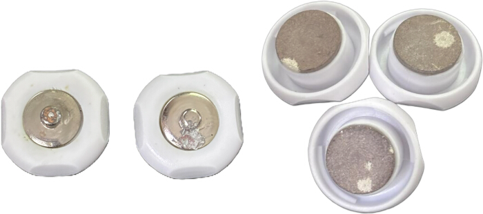
Figure 1: Deteriorated Ag/AgCl electrodes. Ag/AgCl electrodes exhibiting deterioration resulting from improper storage and drying, rendering them unsuitable for further use. Please click here to view a larger version of this figure.
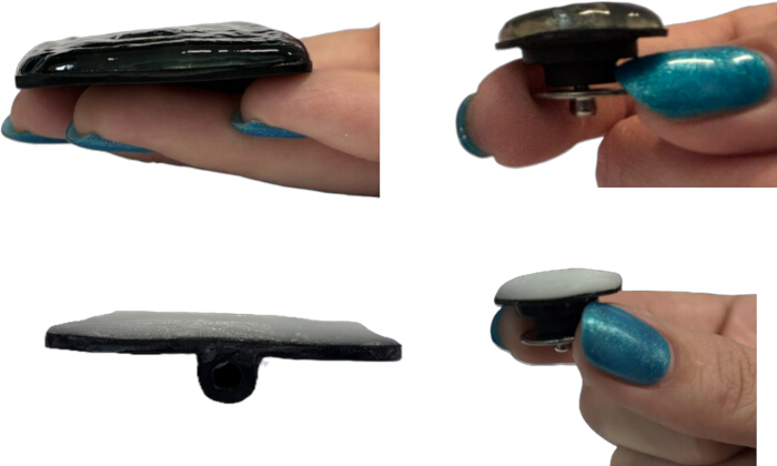
Figure 2: Correct application of conductive medium. Representative examples showing the appropriate amount and distribution of conductive medium for small and large stimulation electrodes. Please click here to view a larger version of this figure.
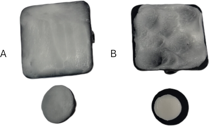
Figure 3: Correct and incorrect conductive paste application. (A) Correct conductive paste application, demonstrating uniform and complete coverage of the electrode surface. (B) Incorrect conductive paste application, illustrating incomplete and uneven coverage. Please click here to view a larger version of this figure.
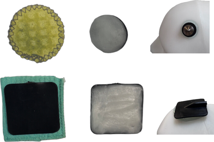
Figure 4: Effect of conductive medium on the effective stimulation area. Schematic illustration showing how the effective electrode contact area changes depending on the conductive medium used. Please click here to view a larger version of this figure.
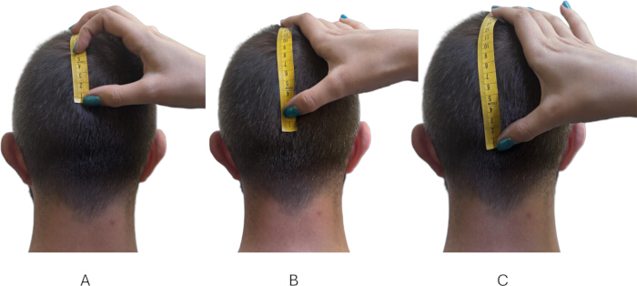
Figure 5: Effect of landmark localization error on electrode positioning. (A) Superior displacement resulting from incorrect identification of the inion. (B) Correct localization of the inion. (C) Inferior displacement resulting from incorrect identification of the inion. Please click here to view a larger version of this figure.
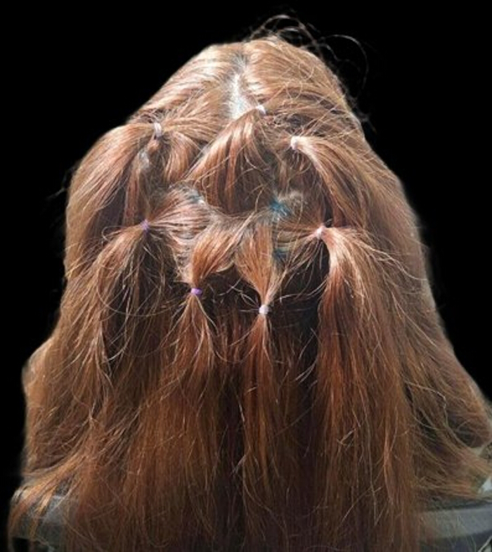
Figure 6: Hair preparation for multielectrode tDCS. Representative illustration of hair preparation for a multielectrode montage over the posterior and occipital scalp in a participant with thick hair. Please click here to view a larger version of this figure.
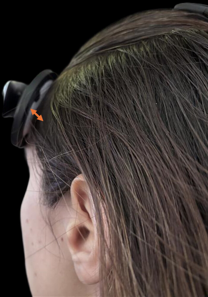
Figure 7: Incorrect electrode positioning during home-based tDCS. Incomplete electrode-to-scalp contact results in unintended current distribution and displacement of the effective stimulation area. Please click here to view a larger version of this figure.
Disclosures
Loading...
$$\rightleftharpoonup{xx}$$
$$\longleftharp{xx}$$,
$$\longrightharp{xx}$$,
Authors have no conflicting interests to disclose.
Acknowledgements
Loading...
$$\rightleftharpoonup{xx}$$
$$\longleftharp{xx}$$,
$$\longrightharp{xx}$$,
Financial support for this research and publication was provided by the Institutional Support from the Ministry of Science, Technological Development, and Innovation of the Republic of Serbia to JB and MS (contract number 451-03-33/2026-03/200015) and to MŽ (contract number 451-03-33/2026-03/200163) at their respective institutions.
References
Loading...
$$\rightleftharpoonup{xx}$$
$$\longleftharp{xx}$$,
$$\longrightharp{xx}$$,
- Nitsche MA, Paulus W. Excitability changes induced in the human motor cortex by weak transcranial direct current stimulation. J Physiol. 2000;527(3):633-639.
- Ko MH. Safety of transcranial direct current stimulation in neurorehabilitation. Brain Neurorehabil. 2021;14(1):e9.
- Antal A, et al. Low intensity transcranial electric stimulation: Safety, ethical, legal regulatory and application guidelines. Clin Neurophysiol. 2017;128(9):1774-1809.
- Antal A, et al. Low intensity transcranial electric stimulation: Safety, ethical, legal regulatory and application guidelines (2017–2025: An update) endorsed by the European Society for Brain Stimulation (ESBS) and the International Federation for Clinical Neurophysiology (IFCN). Clin Neurophysiol. 2026;184:2111436.
- Mutz J, et al. Comparative efficacy and acceptability of non-surgical brain stimulation for the acute treatment of major depressive episodes in adults: Systematic review and network meta-analysis. BMJ. 2019;364:l1079.
- Feng D, et al. Research trends and knowledge mapping of transcranial direct current stimulation in depression: A bibliometric study based on Web of Science, Scopus, and PubMed (2000-2025). Front Psychiatry. 2026;17.
- Sun W, et al. Bibliometric and visual analysis of transcranial direct current stimulation in the Web of Science database from 2000 to 2022 via CiteSpace. Front Hum Neurosci. 2022;16.
- Solomons CD, Shanmugasundaram V. Transcranial direct current stimulation: A review of electrode characteristics and materials. Med Eng Phys. 2020;85:63-71.
- Bjekić J, Živanović M, Filipović SR. Transcranial direct current stimulation (tDCS) for memory enhancement. J Vis Exp. 2021;(175):e62681.
- Villamar MF, et al. Technique and considerations in the use of 4×1 ring high-definition transcranial direct current stimulation (HD-tDCS). J Vis Exp. 2013;(77):e50309.
- Lefaucheur JP, et al. Evidence-based guidelines on the therapeutic use of transcranial direct current stimulation (tDCS). Clin Neurophysiol. 2017;128(1):56-92.
- Bikson M, et al. Guidelines for TMS/tES clinical services and research through the COVID-19 pandemic. Brain Stimul. 2020;13(4):1124-1149.
- Timashkov A, et al. The inconsistent effects of tDCS in rehabilitation and cognitive enhancement: Sources of variability and paths to personalization. Front Hum Neurosci. 2026;20.
- da Silva PHR, et al. Challenges and future directions of transcranial direct current stimulation for depression: Insights from a systematic review and meta-analysis. Braz J Psychiatry. 2025;47:e20243989.
- Horvath JC, Carter O, Forte JD. Transcranial direct current stimulation: Five important issues we aren't discussing (but probably should be). Front Syst Neurosci. 2014;8.
- Woods AJ, et al. A technical guide to tDCS and related non-invasive brain stimulation tools. Clin Neurophysiol. 2016;127(2):1031-1048.
- Truong DQ, Bikson M. Physics of transcranial direct current stimulation devices and their history. J ECT. 2018;34(3):137-143.
- International Organization for Standardization. ISO 10993-1:2018 Biological evaluation of medical devices—Part 1: Evaluation and testing within a risk management process. Available at: https://www.iso.org/standard/68936.html. Accessed July 13, 2026.
- DaSilva AF, Volz MS, Bikson M, Fregni F. Electrode positioning and montage in transcranial direct current stimulation. J Vis Exp. 2011;(51):e2744.
- Hampstead BM, Ehmann M, Rahman-Filipiak A. Reliable use of silver chloride HD-tDCS electrodes. Brain Stimul. 2020;13(4):1005-1007.
- Etienne A, et al. Novel electrodes for reliable EEG recordings on coarse and curly hair. In: Proceedings of the 42nd Annual International Conference of the IEEE Engineering in Medicine & Biology Society (EMBC); Montreal, Canada; 2020. Available at: https://doi.org/10.1109/EMBC44109.2020.9176067.
- Utz KS, Dimova V, Oppenländer K, Kerkhoff G. Electrified minds: Transcranial direct current stimulation (tDCS) and galvanic vestibular stimulation (GVS) as methods of non-invasive brain stimulation in neuropsychology—a review of current data and future implications. Neuropsychologia. 2010;48(10):2789-2810.
- Saturnino GB, et al. SimNIBS 2.1: A comprehensive pipeline for individualized electric field modelling for transcranial brain stimulation. In: Makarov S, Horner M, Noetscher G, editors. Brain and Human Body Modeling: Computational Human Modeling at EMBC 2018. Springer; Cham, Switzerland; 2019:3-25. Available at: https://doi.org/10.1007/978-3-030-21293-3_1.
- Huang Y, Datta A, Bikson M, Parra LC. ROAST: An open-source, fully automated, realistic volumetric approach-based simulator for TES. In: Proceedings of the 40th Annual International Conference of the IEEE Engineering in Medicine and Biology Society (EMBC); Honolulu, HI, USA; 2018:3072-3075. Available at: https://doi.org/10.1109/EMBC.2018.8513086.
- Herwig U, Satrapi P, Schönfeldt-Lecuona C. Using the International 10-20 EEG system for positioning of transcranial magnetic stimulation. Brain Topogr. 2003;16(2):95-99.
- Koessler L, Maillard L, Benhadid A, et al. Automated cortical projection of EEG sensors: Anatomical correlation via the international 10-10 system. Neuroimage. 2009;46(1):64-72.
- Rich TL, Gillick BT. Electrode placement in transcranial direct current stimulation—How reliable is the determination of C3/C4? Brain Sci. 2019;9(3):69.
- Joodaki M, et al. A patient-specific, 3D-printed neurostimulator enabling focal transcranial electrical stimulation and EEG at home. J Neuroeng Rehabil. 2025;22(1):248.
- Hampstead BM, et al. Personalized 3D-printed headgear for multi-electrode transcranial electrical stimulation. J Vis Exp. 2025;(223):e68815.
- Charvet LE, Kasschau M, Datta A, et al. Remotely supervised transcranial direct current stimulation (tDCS) for clinical trials: Guidelines for technology and protocols. Front Syst Neurosci. 2015;9:26.
- Guidelines for module-specific training and certification in Transcranial Magnetic Stimulation and low-intensity Transcranial Electric Stimulation. Available at: https://sb9ff16db593a4b75.jimcontent.com/download/version/1758895154/module/12434678221/name/ESBS_certification_Guidelines.pdf
Reprints and Permissions
Request permission to reuse the text or figures of this JoVE article
Request Permission